David Freer's story in the Ring of Fire anthology "Lineman for the Country" described the beginnings of wired telecommunications in the 1632 universe and the founding of AT&L. Like any good story, much of the technology was mentioned, but not described in detail. This article seeks to fill in the gaps in that story, and provide a glimpse into the development of non-radio telecommunications in the USE. This article will not attempt to go into the details of the history of various types of telecom. Please see the references at the end for such history.
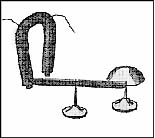
You have used a telegraph. You don't know that, but it's true. Have you ever stood inside your house and flicked the lights on and off to signal to someone in the driveway? Have you ever pressed a doorbell and had a bell inside the house go Ding? You, my friend, have used a telegraph! At its base, a telegraph is nothing more than a doorbell. Press a button here, and something makes a sound "over there." The very first telegraph, made by the famous American scientist Joseph Henry, used a switch and an electromagnet to move an iron bar and ring a bell.

I just can't write an article about the telegraph without a physics lesson. How does that doorbell ring? The answer took the work of half a century by scientists on two continents. Electricity running through a wire produces a magnetic field. (And vice versa but let's stay focussed here.) If you take a flashlight battery, and hook a long piece of wire to it running up and down, a magnetic compass brought near the wire is deflected from north. Sadly, the compass wiggles slowly and only a little, even if you use a lot of electricity. It certainly won't ring a bell. What did Henry do? He took the wire, covered it with silk so that it did not short out against itself, and wrapped it round and round a horseshoe. As the electricity wrapped around in a circle over and over and over, each bit of wire added its bit of magnetism, and together they did what one small length of wire could not do. More wire allowed more loops and generated more magnetism.
By making up a "code," we can send complex messages using this system. The simplest code is just to count letters. You can do this with a doorbell. One ding indicates a step along the alphabet. So, the message "abc" would be sent ding, ding-ding, ding-ding-ding.
This simple code is very inconvenient. Sending a "Z" requires pressing the doorbell button twenty-six times. Samuel Morse and others came up with a number of clever ways to make the process shorter. The most important was making the system make a sound both when you PRESS the doorbell button AND when you let it go. Ding-DONG or more accurately for Morse's sounder: Click-CLACK. This lets you distinguish long and short presses, and you can make a much better code. (Morse code for "Z" is --.. )
There are several variants on "Morse" code. Two of them are known to be used in Grantville: "International" Morse used by the Ham radio operators, and "Railroad" Morse used by the operators for AT&L. The two codes are slightly different, but many operators are comfortable in either.
So, we have a wire, we have a doorbell button, we have the new weird doorbell that goes click-CLACK, we have a code... DONE! Not hardly. What else do we need to make a commercial telegraph operation?
First, we need wire. Modern telephone and electrical wire is copper, but copper wire alone is weak, and requires too many telegraph poles. The transcontinental telegraph in the US used #8 iron wire at 375 pounds per mile. Sometime after the civil war, the telegraph companies switched to copper-clad iron wire, then to multistranded copper over a steel weight-bearing core. No one in seventeenth-century Europe will be making that any time soon. It's iron for us.
The problem is, iron wire placed up on poles in the air rusts; #8 iron wire hung out by itself alone in typical North American weather rusts through in a year. The solution in the 1860s, and for the USE is to "galvanize" the wire, that is, to coat it with zinc. For every mile of wire, we will need ten pounds of zinc.
This raises another problem. We can't just lay the wire on the ground. We need poles. Iron wire needs the support of twenty two poles per mile. That's a theoretical number, incidentally. In practice, allowing for the effects of terrain, you have to figure that 40 miles needs approximately 1000 poles and 135 miles needs 3500 poles.
The use of fewer poles results in the wire sagging, and if multiple wires are strung from each pole it becomes possible for the wires to touch when swaying in the wind. Live trees make poor telegraph poles for several reasons. They grow, and the wires get pulled, they have leaves and other branches that can short out the wires, and they have sap running through them that acts as a conductor, helping "earth" the signal. Additionally, frequently there's no strong tree where you want one. It's far better to have poles made from dead trees that don't have sap, don't grow, and lack branches. Don't lose count. We need twenty two per mile.
There is another complication. You can't just hang the wire from the pole itself. We need insulators. Wire simply stapled to the pole will work over very short distances (a few miles) when the pole is utterly dry, and the weather is fair. However, the least hint of dew, or moisture or rain, and the wire is "earthed" or shorted to ground. No signal can get through when the water running down the pole carries the electricity into the ground. Insulators prevent the electricity in the wire from reaching the ground.
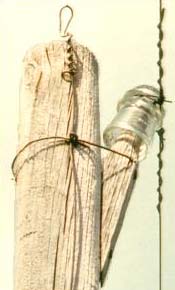
This photo, of a telephone line in western Kansas, shows a Hemingray-17 insulator supporting a galvanized iron wire held on by a loop and wrap of galvanized wire. This is the "standard" installation of a glass or porcelain insulator. Note the design of the insulator. There is a groove near the top, which supports the wire, and then there is a VERY long path down the outside of the insulator, around a "petticoat" or "skirt" and then back up INSIDE the insulator before it finally touches wood. Glass insulators get their surfaces dirty. Soot, from town fires or passing trains is particularly conductive. Insulators crack and water settles into the cracks, and so on. With this skirted cup design there is a long path for any electricity to reach the wood, and in all but the hardest storms, the inside of the insulator is dry and provides a poor path for electricity. Conductive dust and soot wash off glass insulators easily in the rain. The most common modern insulators are porcelain. Porcelain attracts water less than glass, but it is harder to make, and must be vitrified entirely through. Glazed ceramic insulators absorb water if the glaze cracks in the least bit and then fail as insulators.

Good insulators are critical to telegraph (and telephone) operation. Without insulators, maximum signal distances are a few miles and only that in good weather. Fortunately, making insulators is not all that difficult. Even "threaded" insulators which "screw" on to the support rod that holds them can be made by apprentice glassmakers with little training. A few samples should suffice to allow any glass shop to make adequate insulators. The Hemingray 16 shown below is a good example of an advanced design that is simple to cast. It incorporates advanced features such as internal threads, "drip points" and a fluted skirt lip.
At this point, someone usually asks, "Why do we need insulators like that at all? Why not just use insulated wire?" Of course, today we do. If you look at modern telephone lines in most places, the insulators are disappearing as the bare wires are replaced with Teflon and other plastic-coated lines held off their poles with plastic spacers. I hope that I do not need to go into why Grantville will not be making Teflon coated wire or fiberglass for several years.
Second, we need batteries. Wait, it's not second any more is it? Oh well, fourth then. We need batteries. Yes, of course, as long as our main telegraph office is in Grantville, we can power the telegraph from the power lines. But even in the twenty-first century, that's not really done. Up-time telephones are run from batteries that are charged from the power lines. Downtime, unless you're in Grantville, you don't have power lines to charge your batteries from, and you must use 'primary' batteries that, like the batteries you buy at the drugstore, make electricity due to their chemistry, rather than being charged.
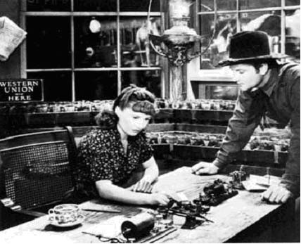
Take a look at this photo from the classic film "Union Pacific" featuring a more-than-comely Barbara Stanwyck, and the ever-handsome Joel McRae.
If you can tear your attention from our attractive heroes for a moment, and look behind them, you will see an array of boxes full of jars with wires going across them.
The producer of Union Pacific, the famous Cecil B. DeMille was a fanatic for accurate historical detail when he chose to be, and this re-creation of a railroad station Western Union main line office is very accurate. Note the acid drips down the front of the wooden battery boxes. There are 10 boxes of 12 cells, and this is typical for a main line telegraph office in the post-civil-war period in the US. One of Mr. Calvin's (played by the accomplished character actor Harold Goodwin) most important duties was the daily care and feeding of the Daniell Cells that powered the telegraph. Our seventeenth-century telegraph is going to need batteries, too.
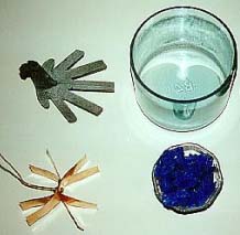
The most common battery used by telegraph companies prior to the mass electrification of the U.S. was a variation on the Daniell Cell called a Crowfoot or gravity cell. It had two advantages. It could be refreshed without complication, and it did not have a drop in voltage as it was used up. The "dry" cells—be they traditional carbon cells or Ni-Cads—that you buy at the store put out less and less voltage as they age. Daniell Cells give constant voltage if they are operating at all, and were therefore called "constant" cells by many telegraphers. The open circuit voltage was about 1.02 V. It is no accident that the cell voltage is close to 1.0 V, since the Daniell cell was the original standard of voltage.

To make a gravity battery a zinc electrode (crowfoot zinc) is hung near the top of a glass jar. A copper electrode (battery copper) is placed in the bottom surrounded by blue vitriol (copper sulfate or "bluestone"). The jar is filled with water and a little sulfuric acid. The electrical action of the cell quickly forms zinc and copper sulfate solutions that remain practically separate because the copper sulfate solution is much heavier, hence the term "gravity" battery. Battery oil or heavy mineral oil is poured over the top to prevent evaporation. This battery has an excellent capacity. An average main line cell will use eight pounds of vitriol, two pounds of zinc and a pound of copper per year. Copper fingers plate out on the zinc, and must be knocked off nightly with a bent rod. (See photo below.)
Each main line station then, will have 120 cells, and use 250 pounds of zinc, 125 pounds of copper, 1200 pounds of copper sulfate (Blue vitriol), 60 gallons of mineral oil, and sixty gallons of sulfuric acid each year. We will need a main line station approximately every 30 miles at first. Eventually, we should be able to run 300 miles on a main line without a relay, but perfecting that kind of technology will take time.
While we're at it, clearly Ms Stanwyck is not staring at a compass wiggling back and forth. She isn't pressing a doorbell button either. What are all those things arrayed in front of her?
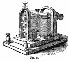
Reading from top right to bottom left there is a sounder. This is a bar, arranged over an electromagnet that wiggles up and down as the electricity of the telegraph goes on and off. As it goes down it makes a distinctive click, and as it comes back up, it makes a distinctive Clack. Thus, every key-up and key-down at the sending end produces a click Clack at the receiving end. Note the adjustable points that allow the sounder to be adjusted for differing line conditions relating to weather, and the condition of the battery at the sending end.

Next is a relay. Relays allow a fading signal reaching one station to be refreshed and sent on to the next station with full vigor. The relay looks a lot like a sounder turned on its side. The magnetic coils have many more turns of wire, and produce a very strong magnetic field for very little electricity. As the relay goes back and forth it acts as a switch for the next piece of the telegraph line.
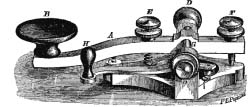
Then a telegraph key. The pressing of the key makes and breaks the circuit, removing the need to manually touch and un-touch the wires. It is a lot easier on your arm than pressing a doorbell button. Note the side-arm switch on the key that allows the circuit to be closed when the key is not in use. Since stations act as relays when they are not sending, and since the same wire is used for sending and receiving, it is important to remember to short your key when you are not using it.
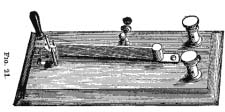
Next are a pair of switches used to take the line in and out of service, and to control if the station is set up as a sending and receiving station, or as a relay.

Finally at the end of the desk is a combination main-line instrument. This is a key coupled to a very sensitive sounder used to directly send and receive on the main line itself without a local relay.
You will notice that most of those instruments (except the key and the switch) feature tightly wound coils of wire. You remember that Joseph Henry figured out that you need to wind coils in order to get a strong magnetic field to make clicks, or to make relays close. Prior to a Beldon Wire company employee's invention of flexible enamel in 1909, there were only two solutions, wrap each layer carefully, placing a thread between each coil of wire and its neighbor and a layer of paper between each layer of the coil, and "silk covered wire." Silk-covered wire was the hottest thing in the wire biz until well into the 20th century. The problem is, we don't have a machine to wrap #30 thin magnet wire with silk. Further, the Grantvilliards need hundreds of feet of #30 wire for each sounder and relay. Making the wire itself is simple enough. German artisans were making wire for centuries before Grantville appeared, but wrapping the wire in silk thread will be tricky, and will require a long process of experimentation. Expect orders through Venice for substantial amounts of silk thread. In the meantime, coils will be laid up by interwinding thread, layering with oiled paper and lacquer (exactly the same way that the generator coils at Hoover dam were made in the 1930s).
How much of these supplies does the USE need? Consider the simplest network that the USE would want to set up as soon as possible. Grantville to Jena. Grantville to Saalfeld. Grantville to Rudolstadt. It is silly to consider going to the work to put up poles and maintain them, and make insulators and so on for a single wire that might be broken or otherwise fail. I presume we will put four wires on a cross bar on each pole. The distances needed are about 39 KM, 10 KM, and 15 KM. Call it forty miles. So, we need a thousand telephone poles, thirty tons of #8 iron wire, a half ton of zinc for galvanizing wire, four thousand insulators, five thousand gallons of creosote or coal tar to paint poles with, a thousand cross bars, four thousand lathe turned insulator spindles (wooden dowels) to screw the insulators onto. Three main line stations need four hundred battery jars, a ton of zinc crowfeet, two hundred fifty pounds of copper crowfeet, one hundred gallons of sulfuric acid, a ton of blue vitriol, and the various sorts of telegraph equipment for each station.
What about the next logical line to Magdeburg? The ground path distance following modern rail lines is 225 KM or 135 miles. This will require thirty-five hundred poles, a hundred tons of iron wire, fourteen thousend insulators and dowels, thirty-five hundred cross beams, two tons of zinc, twenty thousand gallons of creosote, and four more main line relay stations. AT&L will need some serious investment.
Prior to the appearance of Grantville annual European iron production was around 17,000 tons a year, and production in "the Upper Palatinate" (the part of Europe comparable to where Grantville showed up) was in the neighborhood of 2200 tons per year. Zinc production was, of course, zero.
Venice is a thousand kilometers away. A four-plex telegraph line to Venice would consume half the annual production of iron of the area around the USE. Clearly, no such expansion of the telegraph can rely on only down-time extant metals production.
Fortunately, iron production can be scaled rapidly. Consider the following chart of the growth of steel production in the U.S. in the post-Civil-War era:
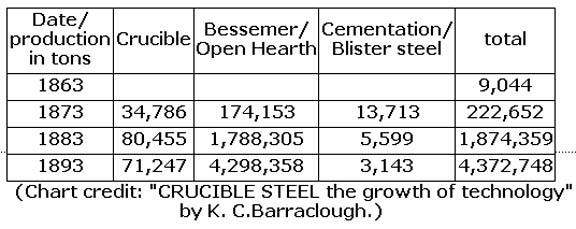
The reality is, of course, that telegraph use of iron disappears as a blip in the curve resulting from the introduction of railroads. Forty-pound main line rail uses more than a hundred tons of iron per mile. The demand for a third-of-a-ton of wire per mile to run alongside the railroad is scarcely noticeable. Between 1830 and 1861 more than thirty thousand miles of railroad were built in the United States. The authors and tech-team of the 1632 series project European iron and steel production to jump one hundred fold over the first ten years after the ROF.
Why the excursion into metallurgy then? The team working on background to the 163x series refers to this as the "Tools to make tools" problem.
• We know how to make a telegraph.
• We know how to make wire for a telegraph.
• We know how to make iron to make wire for a telegraph.
• We know how to make a blast furnace to make iron to make wire for a telegraph.
• We know how to make a Bessemer converter to make steel from the pig iron from the blast furnace to make iron to make wire for a telegraph.
• We know how to make an air pump to pump air into furnaces and converters to make iron to make wire for a telegraph.
• We know how to make a steam engine to power the air pumps to feed the converters and furnaces to make iron to make wire for a telegraph.
• We know how to make boilers to make the steam for the steam engine
• We know how to make the rolling mill to roll the iron plate to make the boiler
• We know how to make the lathe to turn the rolls to make the rolling mill...
•
However, making each of these things takes time. Furthermore, this is not the only chain of need. For example:
• Finding the fire-clay so that you can
• grind the raw materials
• to make the raw brick
• to place into the kiln which you must make
• to make the fire bricks
• to line the blast furnace takes time...
The telegraph has many such chains of need. Zinc, tool steel for machinists, bluestone, sulfuric acid, magnet coils, brass for keys and sounders, springs, insulators, poles, creosote, and battery jars each have their own chains, or in some cases webs of need. Thus the phrase, "Tools to make tools to make tools..."
Assuming you have no better use for the up-time resources, we could extend Grantville's telephone system into Rudolstadt, and run a single line to Jena or Suhl using up-time wire. The first long-distance circuits will be run using salvaged wire that originally led out of the Ring of Fire to places that no longer exist. Many miles of insulated up-time hard copper wire can be salvaged from dead-ended lines.
Depending on your funding, you can build a handful of other telegraph lines using wire made from iron bought in Nuremberg or elsewhere in Europe. You can also produce a spider's web of government telephones in Prague (See Eric Flint's story in Ring of Fire, "The Wallenstein Gambit.")
Beyond that, landline telecommunications will have to participate in, or wait for the expansion of iron production in Europe that will follow the demand for rail and wire and telegraphs and telephones. This is why all the discussion in the various 1632 books to date about long-distance telecommunications rely on radio. Up-time radios are a limited resource, but they are more available than the wire to build a telecom network across Europe.
What then of Prague? Why did Wallenstein go to the trouble of building Europe's second telephone exchange? Only Eric can be sure. The tools-to-make-tools discussion allows us to understand why the owners of AT&L said "Yes!" to a project that was a major distraction from setting up the European telegraph network. They needed the money.
We can't do much to help understand the "why" of the telephone network in Prague, but we can pursue the "what." What was done, and how was it accomplished?
A telephone exchange has three major advantages, and a host of disadvantages over a set of telegraphs.
The advantages are simple enough:
• Anyone can learn to use a telephone in about one minute.
• Telephones send messages as fast as one may talk.
• Using a telephone exchange, any telephone instrument can be attached to any other.
Telegraphs require trained operators, they are "line" instruments, one attached to the next to the next, you can't "dial" a telegraph, and they are comparatively slow. Average commercial operators transmit twenty to forty words per minute. Try speaking one word every two seconds, and see how slow it feels.
But these advantages come at a substantial cost. Telephone exchanges are complex, as are telephone instruments.
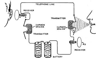
Consider a two telephone circuit. A set of batteries provides current in a loop. The action of sound waves acts on a diaphragm that compresses carbon granules and creates electric waves that mirror the sound waves. This causes the receiver at the other end to be magnetized in a waving manner, which attracts and repels the diaphragm that vibrates air so that you can hear the sounds at the other end.
Note, however, that BOTH receivers are in the circuit, and BOTH microphones are in the circuit. In early telephones, much of the power was wasted in producing sound at the receiver of the person speaking. To avoid this requires a bit of electronics called an anti-side tone circuit. How those work is beyond the scope of this discussion but they are the reason you don't hear yourself when you talk on the phone.
There is, of course another problem. You don't want to sit all day with the phone pressed to your ear just in case someone might speak to you. (Unless you're a party-line snoop but that, too, is a subject for another day.) We need a way to signal that someone wants to talk. So, our phone just became more complex.
This diagram outlines the circuits in a classic three-box crank wall phone like you have seen in movies and television:
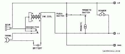
This phone has three important elements. The transmitter and receiver (on the left in the diagram, and in the middle of the phone pictured below), the ringer and magneto (on the right in the diagram and at the top in the phone below) and the local battery, which is a Daniell Cell battery in the slope topped box at the bottom of the phone below, in the middle of the diagram above.

When the phone is "on hook" or hung up, the magneto and ringer are connected to the line and the battery is disconnected. If you crank the magneto, 100V signals are sent to the central office. If the central office cranks THEIR magneto, 100V signals are sent to this phone, and the bell rings.
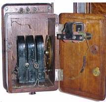
Here's a view inside the top box showing the magneto, and the back of the ringer:
The magneto consists of three horseshoe magnets with a finely wound coil of wire (more of that silk-covered wire) inside, with a gear arrangement to cause the magneto to turn twenty times for each turn of the crank outside the box. The ringer has two coils (more silk) which alternately push and pull the bell clapper as the AC ringer current pulses through the phone.
Silk importers are going to be doing a bang-up business huh? Why silk? Because it's thin, allowing the wires to be placed very close to each other, and because prior to the invention of rayon, silk was the only monofilament thread. Silk thread is not "spun" from bundles of short fibers. It is a single long fiber produced by a silkworm and uncoiled from a cocoon. The silk thread does not have any holes in it. It isn't "lumpy" at a microscopic level. It is smooth and covers the wire evenly. Cotton, or linen, or hemp thread can be used to cover wire, but the coils are more loosely spaced, and occasional shorts occur where the lumps in the thread line up and open a gap in the insulation.
One of the tools to make tools Grantvillers and their allies desperately need to invent is a machine to wrap silk thread around thin copper wire, or a chemist needs to reconstruct how to make flexible enamel.
We now have a telephone, and the mechanism to ring a bell at need. But there is still an element missing. One telephone, or two telephones does not a phone system make. It is necessary to wire up many phones together. However, it would be bad if all phones' bells rang any time any phones' bell rang. Further, it would not work. The ringing impulse would be wasted. We need a way to connect together JUST the phones of interest. Hello Central!

Pictured above is a small magneto ringing central office exchange cord-board. Each socket in the board has a small metal flag above it that is usually black
The process of operating the board is not complex. To pick up an incoming call, the operator hears her bell ring, and notes which signal flag has fallen (and turned red) in the socket array. She plugs into that socket, resets the flag and talks with the caller on her handset. Once she is told who the caller wishes to be connected to, she rings out to the target caller.
To ring a customer, an operator inserts a plug from the right hand bank into a customer's socket, and spins the crank, ringing the customers phone. Pulling the switch in front of the plug towards the operator connects the operator's handset so that she can talk with the person who answers. When she has an answer, she flips her switch forward, connecting the pair of plugs. When the callers hang up, the flag on the socket falls again, and the operator knows to unplug them. On this board, up to nine simultaneous calls can be wired. This board also supports three "long distance" trunks to connect to OTHER exchanges elsewhere. (It is universally the case, even today, that no phone system can support more than a small fraction of its phones having a call at the same time.) This board supported 150 lines. A single line can have up to eight phones attached to it. This saves metal, but is inconvenient for the subscribers since anyone can snoop on their neighbors' calls on the "party" line. Calls for different houses on a party line are distinguished by a different pattern of ringing. (My grandmother's house was long-short-short.)
Fortunately, once we have built phones, the plugboard requires nothing but down-time craftsmanship and patience. No inventions or tools are particularly needed excepting, of course, insulated wire (more silk.)
Each plug has wires running to it, each socket has a "flag" which is dropped by a pin retracting when ringer voltage is applied, so there has to be a coil of (silk-covered) wire behind the flag to pull the pin on each socket. Then, each plug has to have a (probably wooden) insulating handle, and a cord of braided copper wires (two of them) covered individually with—you guessed it—silk, and then covered together with a fabric tube to keep them from binding. The switches are simple brass levers and contacts. Oh, more zinc. Oh well.
This magneto exchange is "local." The telephones have a limited range of a few dozen miles. "Long Distance" telephones require balanced lines, impedance matching, and amplifiers, all of which are beyond the capacity of the USE's engineers for the short-term future. For the time being, communication between cities will have to be handed over to Morse code operators be they radio or wire line operators.
For the short term, that is the state of telecommunications in the USE and the 1632 series. There will be a few "local" telephone exchanges, in Grantville, in Magdeburg, and Prague. There will be "long lines" telegraph between cities as the money becomes available and as the pressure of the railroads increases steel production, and there will be radio.
I hope this brief introduction to telecommunications helps with an understanding of the difficulties and opportunities facing AT&L, and other telecom developers in the world after the Ring of Fire.
The photos of western electric phones and the telephone circuit diagrams above are from:
OLD TELEPHONES How to Repair and Rebuild Them by
Jeffrey Race
Cambridge Electronics Laboratories
20 Chester Street
Somerville, Massachusetts 02144 USA
Telephone +1 617 629-2805 Telefax +1 617 623-1882
camblab@attglobal.net www.camblab.com
The best source for information on telegraphic practice prior to 1900 is probably Pope, from whose work the drawings above come.
http://www.insulators.com/books/mpet/
Excellent site detailing telegraphy during the American Civil War
http://www.unitedstatesmilitarytelegraph.org/
and another
http://www.civilwarhome.com/telegraph.htm
A good general history of telecommunications can be found at
http://www.privateline.com/TelephoneHistory/History1.htm
I can't believe you don't know the story of Joseph Henry, but just in case
http://www.si.edu/archives//ihd/jhp/index.htm
(Yes, this has two slashes in the middle.)
More than you ever wanted to know about insulators at
An excellent phone museum
http://www.woodstelephonepioneers.org/museum/
The last central office magneto hand crank phone system in the U.S. to go dial.
http://www.privateline.com/TelephoneHistory5/History5.htm